A breadboard is one of the most essential tools in electronics for creating, testing, and modifying circuits without soldering. Whether you’re a student, hobbyist, or engineer, understanding where does the current travel in a breadboard is crucial for designing functional electronic circuits. Knowing how the current flows helps you connect components correctly, avoid short circuits, and debug electrical issues efficiently.
Before we dive deeper, you can read more about the basic concept of electric current on Wikipedia and about breadboards themselves on Wikipedia.
Understanding the Structure of a Breadboard
To know where the current travels in a breadboard, it’s important to understand its internal structure. A breadboard is not just a piece of plastic with holes—it’s a grid of metal clips connected in specific patterns underneath the board.
A typical breadboard has:
- Power Rails (Long Lines on the Sides)
- These are the long columns that run along the sides of the board, usually labeled with “+” (red line) for positive voltage and “–” (blue or black line) for ground.
- Power rails are used to distribute power (voltage and ground) throughout the board.
- Terminal Strips (Main Area in the Middle)
- This is the main working area where components like resistors, transistors, and LEDs are placed.
- Each row (horizontal group) of five holes is electrically connected underneath.
- Center Divider (The Middle Gap)
- The long gap in the center separates the two halves of the board.
- This space is designed to fit integrated circuits (ICs) so that each pin is on a different row and not connected directly to the opposite side.
These three sections determine how and where the current flows within the breadboard.
How Current Flows Through a Breadboard
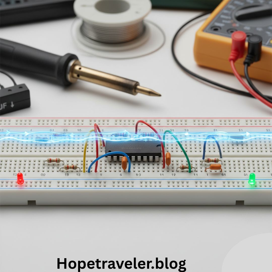
When you power a breadboard, current flows from the positive terminal of the power supply into the breadboard’s power rail and travels through the components connected in the circuit before returning to the negative terminal.
Let’s break it down step-by-step:
1. From Power Source to Power Rail
You connect your power source—like a battery pack, power adapter, or Arduino board—to the breadboard.
- The positive terminal connects to the “+” rail.
- The negative terminal connects to the “–” rail (ground).
Now, the rails act like highways for the current—ready to supply power to all components across the board.
2. From Power Rail to Components
When you connect a component (e.g., an LED with a resistor) to the breadboard, you use jumper wires to connect from the power rail to one of the terminal strip rows.
Each row of five holes on one side of the central divider is connected internally. So if you insert a resistor lead into hole 1A, holes 1B, 1C, 1D, and 1E are all connected to that same node.
Thus, current travels horizontally across those five connected points.
3. Across Components to the Other Side
If you’re using an IC (Integrated Circuit) or connecting across the divider, current must travel through your component or jumper wire to reach the other half.
For instance, when an LED’s anode (positive leg) is connected to a resistor on one row, and its cathode (negative leg) connects to ground on another, the current flows from:
Power (+) → Resistor → LED → Ground (–)
That’s the basic circuit loop, and understanding it is the foundation of where the current travels in a breadboard.
The Hidden Metal Strips
Underneath the breadboard’s surface are metal clips arranged in a specific pattern that determines current flow.
Here’s what they look like:
- Horizontal Strips: Each row of five holes in the terminal area is connected horizontally.
- Vertical Strips: Power rails are connected vertically along the entire length of the board.
When a wire or component is inserted into a hole, its metal lead touches the metal clip beneath. That’s how electrical contact is made, allowing current to flow from one component to another.
In short:
- Current travels vertically through power rails.
- Current travels horizontally across the terminal strip rows.
Understanding Current Direction
Electric current always travels from positive to negative in a conventional sense. (In reality, electrons flow from negative to positive, but conventionally we follow the opposite.)
So, in a breadboard:
- Current leaves the positive terminal of the power supply.
- It moves through wires and components (like resistors, LEDs, etc.).
- It finally returns to the negative terminal (ground).
This continuous path is called a circuit loop. If this loop is broken anywhere, current stops flowing.
Example: Current Flow in a Simple LED Circuit
Let’s take a practical example to visualize where current travels in a breadboard:
Components:
- 1 LED
- 1 Resistor (220Ω)
- 1 Power source (5V)
- Jumper wires
Steps:
- Connect the 5V power supply to the + power rail.
- Connect the ground (GND) to the – power rail.
- Insert the resistor into one terminal strip row (say row 10A).
- Insert the anode (long leg) of the LED into the same row (10E).
- The resistor and LED are now connected in series.
- Insert the cathode (short leg) of the LED into another row (11E).
- Use a jumper wire to connect row 11A (same row as LED cathode) to the – power rail.
Now, current flows as follows:
5V (Power Rail) → Resistor → LED → Ground (GND Rail)
The LED lights up because current travels correctly through the circuit.
Common Mistakes and How They Affect Current Flow
When building circuits, incorrect placement can prevent current from flowing or cause short circuits. Let’s look at common errors:
- Connecting Components in the Same Row (Same Node)
- If both ends of a resistor or LED are placed in the same horizontal row, they are electrically connected at both ends—so no current flows through the component.
- Misusing Power Rails
- Not all breadboards have continuous power rails. Some have breaks in the middle, meaning the rails are divided into two sections. If not connected, one side won’t receive power.
- Crossing Power and Ground
- Accidentally connecting “+” and “–” directly can cause a short circuit, potentially damaging your components or power supply.
- Loose or Oxidized Contacts
- Dust or wear on the breadboard can prevent proper electrical contact, disrupting current flow.
Visualizing the Flow of Electricity
Imagine water flowing through pipes—current works the same way.
- The battery or power supply acts as a water pump.
- The wires are the pipes.
- Resistors and LEDs act as valves or filters controlling flow.
- The breadboard is the network of pipes that connects everything together.
When the circuit is correctly built, current flows smoothly, lighting up LEDs, powering sensors, or running motors.
How to Test Current Flow
To confirm where current travels in a breadboard, you can use a multimeter:
- Set it to measure continuity or voltage.
- Touch one probe to the power rail and another to a point in the circuit.
- If current is flowing, you’ll see voltage or hear a beep (for continuity).
This helps verify connections and detect where current stops flowing.
Advanced Breadboard Powering Tips
When working on complex circuits, managing current flow becomes more critical. Here are some expert tips:
- Use color-coded jumper wires: Red for positive, black for ground.
- Bridge split rails: Use short jumper wires to connect top and bottom rails so both sides receive power.
- Add decoupling capacitors: These stabilize current flow for sensitive components like ICs.
- Use external regulators: To provide steady voltage and prevent overcurrent damage.
The Science Behind It: Electrical Conductivity
The breadboard’s metal strips are usually made of nickel-plated phosphor bronze—a highly conductive material that allows smooth current flow.
When you plug in a component, its lead physically touches the metal clip, completing the path for electrons to move. The breadboard thus acts as a temporary circuit board, where current flows just like in a permanent printed circuit board (PCB), but with flexibility to make changes easily.
Conclusion
So, where does the current travel in a breadboard?
It travels through the metal strips underneath the holes—vertically in the power rails and horizontally across the terminal rows. Current moves from the positive rail, through components placed across connected rows, and finally back to the negative rail (ground), completing the circuit.
Understanding this flow is essential for building efficient and safe electronic circuits. Once you grasp it, you can design complex projects like sensors, microcontroller systems, and robotics—all starting from a simple breadboard.
If you want to go further, explore more about the science of electric circuits on Wikipedia.